Other articles in this series
ASSEMBLING A TELESCOPE FOR THE FIRST TIME
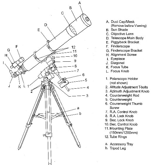
The diagram above
shows a typical telescope assembly with the main parts identified.
First a safety notice.
If assembly is to be conducted outside in daylight then the Dust Cap [A]
must be fitted to avoid sunlight entering the tube and causing damage to the
components or injury to the person who is assembling the telescope.
In this article the guidance is of a general nature as
each telescope has differences in design depending on the supplier and the
components used. Illustrations are from
the assembly of a Skywatcher 120mm f1000 refractor fitted to an EQ5
Equatorial Mounting and Field Tripod.
On receiving the new telescope open the package and check
that all sub-assemblies and components are present according to the list in the
instructions. Read the instructions as
these may be good and enable the telescope to be assembled without any
problems. The guidance in this magazine
should be used as additional help or if problems are encountered.
When using these instructions first identify the
equivalent sub-assemblies and components supplied with those shown in the
diagram above, they may not be identical but should look similar. When this has been done assembly can begin.
First assembly can be done indoors or
outdoors but if it is to be done outside in daylight take special note of the
safety notice at the beginning of this article.
First set up the tripod stand [comprising a & b] (from the diagram above). For the first assembly it is not necessary to
accurately level or align the stand.
It does however help to start with the stand roughly level and oriented
in a north south alignment. (Figures 1
& 2 show an alternative design.)
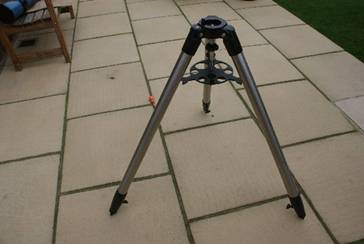
Figure 1 A typical Field
Tripod with a Leg Spreader
Position the Leg Spreader on the lower Hand Nut
with the strengthening webs at the bottom and the leg notches located on the
legs. Tighten the Hand Nut until the
legs are rigid.
Do not over tighten the Hand-Nut or it may
damage the Leg Spreader.
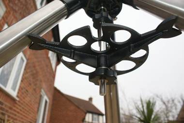
Figure 2 View of the
underneath of the Leg Spreader
Using a compass to identify north, rotate the
tripod so that the marked north position is pointing approximately north.
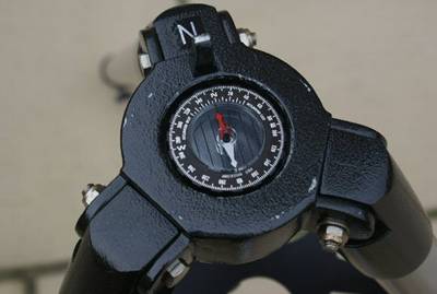
Figure 3 Using a compass to align the stand to north
It will be necessary to align and level the
stand more accurately for first observing session. We will be covering this aspect in the first
use of the telescope article.
On the tripod mounting head shown in Figure 3
there is a fine alignment peg at the north position. This is used to carry out fine alignment on
north for observing. During first
assembly if a notch is present make sure the two adjusters on the equatorial
mounting base are unscrewed so they do not interfere with fitting.
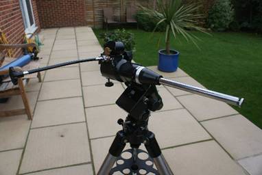
Figure 4 The
Equatorial Mounting fitted to the Tripod Head
The Equatorial Mounting Securing Hand Grip
can be seen above the Leg Spreader in Figure 2.
If the Equatorial Mounting is a heavy model an extra pair of hands may
be required for this operation. Lift the
Equatorial Mounting and position it on to the Tripod Mounting Head. Ensure the fine adjusting screws do not hang
up on the North location peg (if present).
Raise the Equatorial Mounting Securing Hand Grip and rotate it until the
thread engages into the thread in the Equatorial Mounting base. Tighten the Equatorial Mounting Securing Hand
Grip to secure the Equatorial Mounting. (Securing arrangements may vary.)
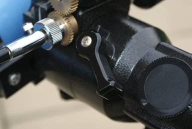
Figure 5 RA Lock Knob
[8] similar to Dec Lock Knob [9]
Before proceeding with the next operation
tighten the RA Lock Knob [8] and the Dec Lock Knob [9] to prevent inadvertent
rotation. If not already fitted (as
shown in Figure 4) fit the Counterweight Rod [4].
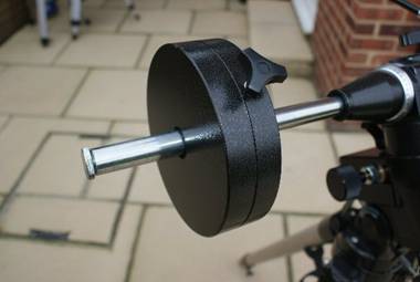
Figure 6 Counter
Balance Weight and Rod
Remove the Counterweight safety screw from
the end of the Counterweight Rod. Slide
the Counterweight on to the Counterweight Rod and secure using the
Counterweight Thumb Screw [6]. Re-fit the Counterweight safety screw on to the Counterweight Rod. The Tripod and Equatorial Mounting are now
ready to receive the Telescope Optical Tube Assembly.
If the type of tripod
shown in the opening diagram is supplied then it should be assembled as
follows: Open the Tripod Legs [a] while
raising the hinged Spreader Arms. When
the Spreader Arms are fully extended position the Accessory Tray [b] on top of
the Spreader Arms. Align the holes in
the Accessory Tray with the holes on the Spreader Arms and fit the securing
screws. Pull the legs out to fully
tension the legs and produce a rigid assembly that is ready to fit the
Equatorial Mounting.
FITTING
THE OPTICAL TUBE ASSEMBLY TO THE MOUNT
Most telescopes use a system of Tube Mounting
Rings [12], Mounting Plate [11] and a Dove Tail location to fix the Optical
Tube Assembly (telescope) to the mounting.
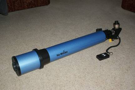
Figure 7 The Optical Tube Assembly
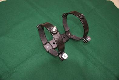
Figure 8 The
Tube Mounting Rings and Mounting Plate
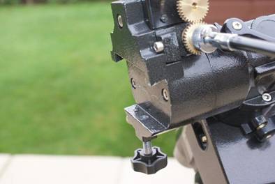
Figure 9 The
Dovetail Locator on the Mounting
Before starting to
assemble the components to fit the Optical Tube Assembly to the Mounting, the
mounting must be positioned in the orientation in which it will be used. This does depend largely on the design of the
mounting. We must ensure the Drive
Control Knobs do not interfere with the movement of the telescope and they are
easily accessible when using the telescope.
Most observing will be done with the telescope pointing towards the
south with a view sweeping from east to west.
So it helps to set up as we expect to observe.
To continue the
assembly process we need to fit the finder.
There are two types of finder supplied with modern telescopes. These are: a small conventional telescope or
a Red Dot Finder. Conventional telescope
finders may typically be 7 x 30 or 9 x 50 (magnification x aperture) and other
combinations.
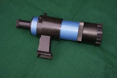
Figure 14 A typical 8
x 50 Finder Scope and Mount
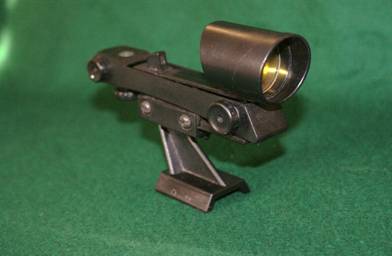
Figure 15 A Red Dot Finder
To assemble the
Finder Scope shown in Figure 14 fit the rubber ring into the groove on Finder
Scope tube. Loosen the two adjusting
screws on the Mounting Tube and pull up the spring loaded location pad. Push the Finder into the Mounting Tube until
the rubber ring engages into the groove on the inside of the mounting
tube. Release the spring loaded location
pad and tighten the two adjusting screws until they lightly hold the Finder
Scope centrally. Fit the finder into the
Dove Tail mounting on the telescope and tighten the securing screw.
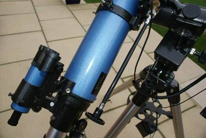
Figure 16 A Red Dot
and Finder Scope fitted
BALANCING THE TELECOPE
The main assembly
sequence is now complete and the new telescope is almost ready to use. However before use we need to make a few
adjustments to balance the telescope.
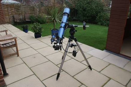
Figure 17 The completed telescope assembly
First we can balance
the Optical Tube Assembly. To make sure
the balance is correct we need to fit an Eyepiece into the Focuser
Assembly. Loosen the small thumb screw
on the side of the focuser tube. If
fitted remove the dust cap from the focuser and fit the Eyepiece. Tighten the thumb screw to secure the
Eyepiece. Make sure the telescope is not
pointing towards the Sun and remove the Dust Cover from the end of the Tube.
Support the tube and
release the Dec Lock. Carefully let the
tube swing up or down a little to indicate which end is heaviest. Slacken off the Tube Mounting Ring Clamp
Screws. While rotating the tube back and
forth slightly, slide the tube through the Tube Mounting Rings towards the
lighter end. Let the tube swing up and
down again to check the balance. Repeat
the process until the tube does not swing up or down. Re-tighten the Tube Mounting Ring Clamp
Screws and the Dec Lock.
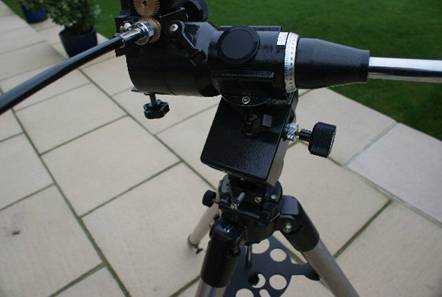
Figure 18 The RA axis on the Mounting
To balance the RA
axis support the tube assembly (make sure the Dec is locked) and the Counter
Weight Rod is horizontal as shown in Figure 18.
Support the Optical Tube Assembly to prevent inadvertent rotation. Release the RA lock and allow the Tube and
Counter Weight Assembly to rotate slightly.
If the Optical Tube Assembly moves down move it back to horizontal and
engage the RA Lock. Loosen the Counter
Weight Clamp Screw and slide the Counter Weight further along the Rod. Repeat until rotating assembly is balanced.
FITTING
ANY EXTRA COMPONENTS
The telescope is now ready for use and we
will be looking at the final adjustments that need to be made in the first use
article. In the next article we will be
looking at setting the telescope up for observing the first time.
Some telescopes can have additional upgrade
equipment supplied when purchased at additional cost. Alternatively upgrades can be bought
separately at a later stage. Here are a
few words about those extra components that are most often supplied with the
telescope package.
One very useful extra is an electric drive on
the RA axis. This allows the telescope
to track an object as it appears to move across the sky due the rotation of
Earth on its axis.
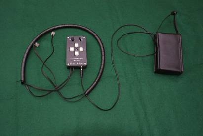
Figure 19 A RA and
Dec Drive System
There are many ways that the drive system is
fitted depending on the design of the mounting.
Some have a small motor that replaces the RA Control Knob [7]. Some mountings have a special motor bay
designed into the Equatorial Mounting.
The telescope assembled in this article does have a special bay for the
RA Motor. It also has a drive on the Dec
axis but this is a relative luxury compared to the RA Drive. The Drives with the Control Box and Battery
Pack shown in Figure 19 were supplied with the telescope.
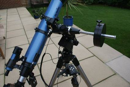
Figure 20 The telescope with RA and Dec Drives fitted
In Figure 20 the
Control Box and Battery Pack are shown between the legs of the Tripod. The RA Dive Motor is housed in the square
black compartment with the cable connected. See Figure 18 for a closer view of the RA Motor Bay. The Dec Motor is fitted on the top of the
Mounting close to the Dove Tail location. It can be seen closer in Figure 9 and 18. The motors can be disengaged using the silver
knurled knob on the RA and Dec Hand Control Knobs.